

Rail Transfer Cart
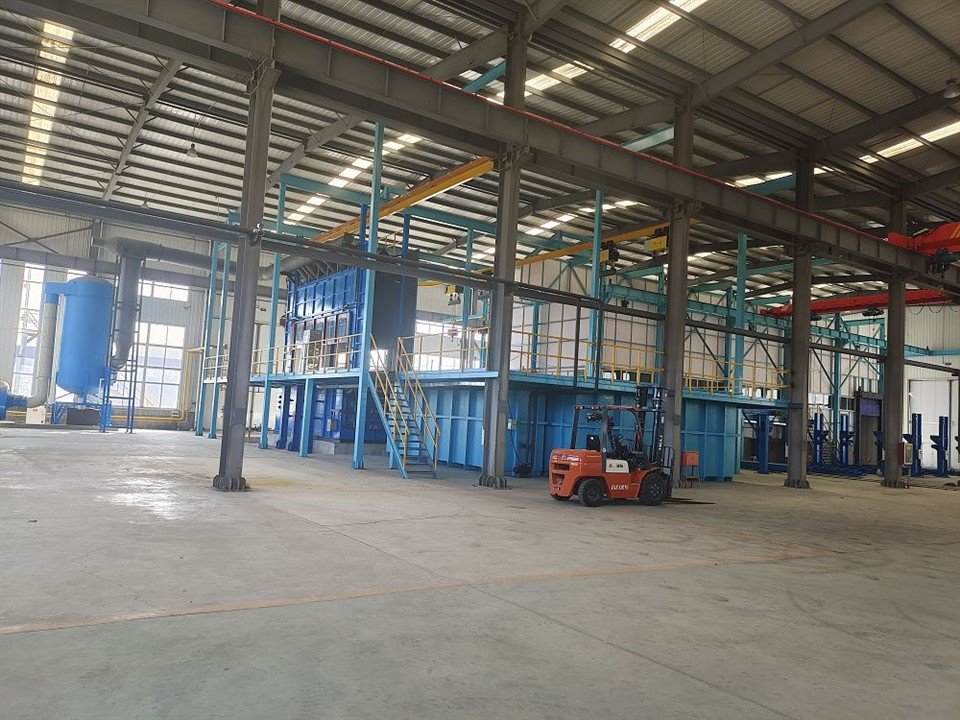
Name: Rail Guided Transfer Cart
Specification: The equipment is customized according to the product type and load capacity required by the user.
Overview:
This transfer cart is designed for handling hot-dip galvanized structural components, power fittings, steel pipes, profiles, and similar workpieces, with a load capacity of 1 to 16 tons.
The cart can be powered via wired or wireless power supply systems. Control options include a fixed control panel or remote control operation. The cart body is fabricated from welded steel structure and coated with anti-corrosion resin paint. The driving system consists of an electric motor and a reducer.
Application Parameters
|
Application Position |
Material |
Energy Source |
Application Scope |
|
Transfer of Black and Galvanized Workpieces |
Metal |
Electricity |
Transport of untreated workpieces to the pickling room and transfer of finished (galvanized) workpieces |
Loading and Unloading Rack
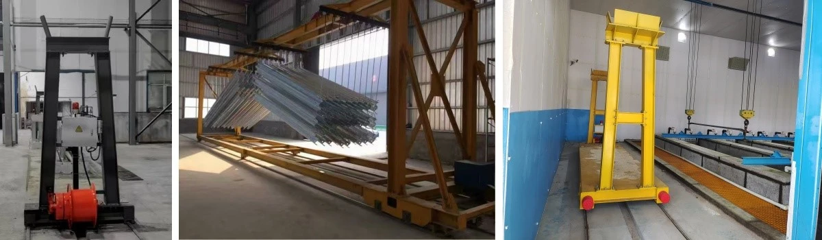
Name: Loading and Unloading Rack
Specification: The equipment is customized according to the maximum workpiece length, weight per batch, and product type required by the user.
Overview:
This equipment is designed for loading and unloading operations of structural components, power fittings, steel pipes, profiles, and similar workpieces in hot-dip galvanizing processes.
It is used to suspend workpieces on lifting frames for pre-galvanizing preparation or to place galvanized workpieces on the rack for unloading. The loading and unloading rack is equipped with a lifting mechanism that can move up and down, facilitating convenient handling, hanging, and removal of workpieces.
Application Parameters
|
Application Position |
Material |
Energy Source |
Application Scope |
|
Workpiece Loading and Unloading |
Metal |
Electricity |
Loading of untreated (black) workpieces and unloading of galvanized (finished) workpieces |
Pickling Room
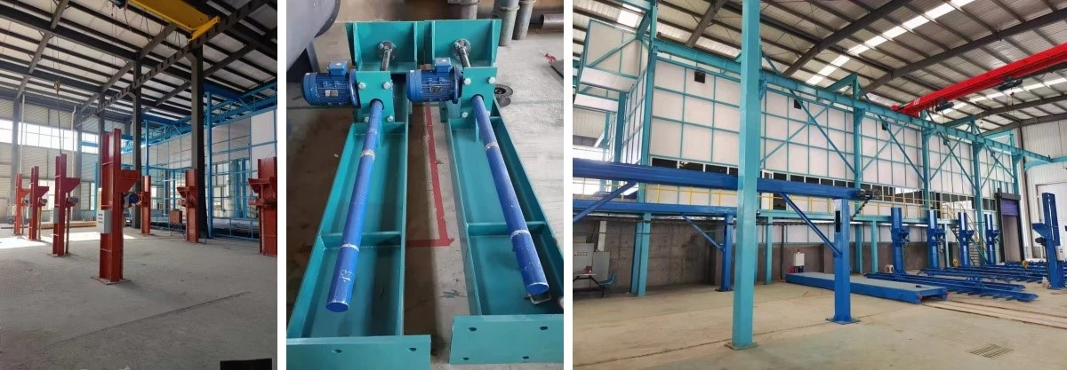
Name: Enclosed Pickling Room For Structural Components Automatic Hot-dip Galvanizing Production Line
Specification: The equipment is customized according to the maximum workpiece length and lifting height required by the user.
Overview:
This system is designed for the pre-treatment of structural components, power fittings, steel pipes, profiles, and similar workpieces in hot-dip galvanizing processes.
All pre-treatment operations, including pickling, rinsing, and fluxing, are arranged a sealed enclosure, effectively isolating the pre-treatment tanks from the main workshop and minimizing the leakage of harmful gases.
The enclosure is constructed with a steel structure, with the exterior coated in polyurea or anti-corrosion resin paint. The interior is lined with FRP or UPVC panels for enhanced corrosion resistance. An acid gas neutralization and filtration tower is installed outside the enclosure to absorb and treat acid fumes before discharge.
Application Parameters
|
Application Position |
Material |
Energy Source |
Application Scope |
|
Exhaust Gas Protection for Pre-Treatment Tanks |
Metal + UPVC |
- |
Collection and controlled discharge of exhaust gases generated from pre-treatment processes |
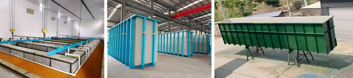
Pre-treatment Tank
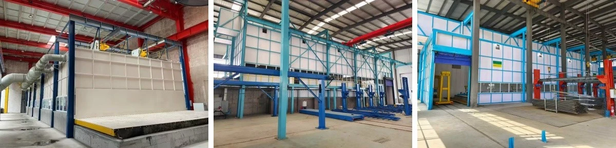
Name: Pre-treatment Cleaning Tank
Specification: The equipment is customized according to the maximum workpiece length, single-batch weight, and product type required by the user.
Overview:
This tank is designed for pre-treatment cleaning of structural components, power fittings, steel pipes, profiles, and similar workpieces in hot-dip galvanizing processes.
The tank can be constructed using various corrosion-resistant material combinations, including:
Acid-resistant granite + epoxy resin + fiberglass (FRP)
PP panels + steel structure + polyurea coating
Steel structure + PE high-polymer materials
Users can select the appropriate material configuration based on actual operating conditions. The material specifications of the pre-treatment cleaning tank are consistent with those used in post-galvanizing water cooling and passivation tanks.
Application Parameters
|
Application Position |
Material |
Energy Source |
Application Scope |
|
Workpiece Cleaning and Passivation |
Metal, PE, PP |
- |
Suitable for pickling, rinsing, fluxing, and passivation processes of workpieces |
Transfer Drying Pit
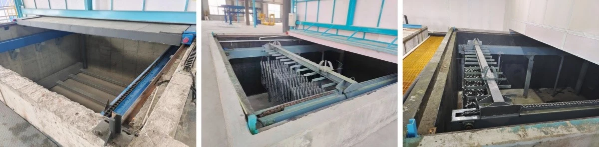
Name: Drying Transfer Area
Specification: The equipment is customized according to the maximum workpiece length, single-batch weight, and product type required by the user.
Overview:
This area is designed for transferring structural components, power fittings, steel pipes, profiles, and similar workpieces after pre-treatment cleaning in hot-dip galvanizing processes.
The transfer zone is equipped with a stainless steel continuous chain conveyor system, which moves the pre-treated workpieces forward and transfers them out of the enclosed pickling room for subsequent processing.
Application Parameters
|
Application Position |
Material |
Energy Source |
Application Scope |
|
Post-Cleaning Transfer |
Stainless Steel |
Electricity |
Transfer of workpieces after cleaning |
Enclosed Dust Hood
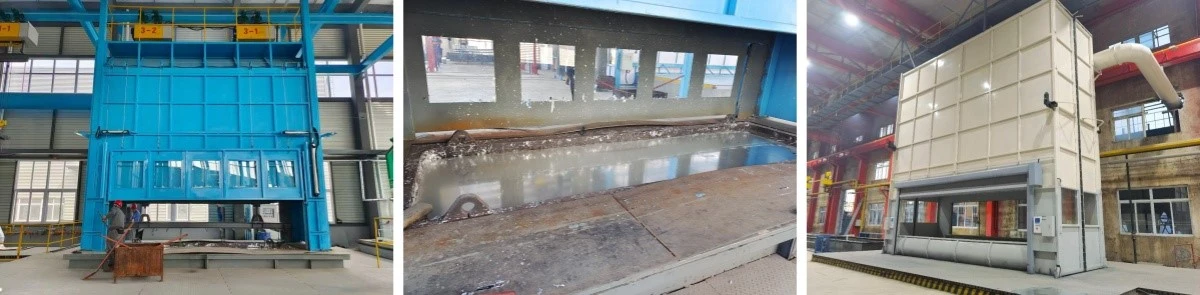
Name: Enclosed Dust Hood
Specification: The equipment is customized according to the specifications of the user's zinc pot.
Overview:
This system is designed for collecting and exhausting zinc fumes generated during the hot-dip galvanizing process of structural components, power fittings, steel pipes, profiles, and similar workpieces.
Zinc fumes are captured through side suction at the upper edge of the zinc pot and top suction via the enclosed dust hood, ensuring organized collection and discharge.
The fume collection chamber is equipped with sealed access doors on both ends for workpiece entry and exit, which are pneumatically operated. Automatic lifting doors are installed on both sides of the working area of the collection chamber, allowing convenient access for dust cleaning and maintenance operations.
Application Parameters
|
Application Position |
Material |
Energy Source |
Application Scope |
|
Above Zinc Pot |
Steel Structure |
Electricity + Pneumatic |
Collection and controlled treatment of zinc fumes and dust from the galvanizing process |
Zinc Pot Furnace
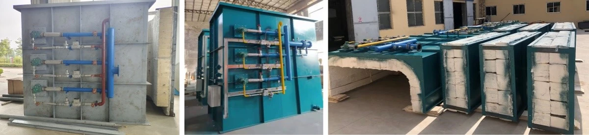
Name: Zinc Pot Furnace
Specification: The equipment is customized according to the specifications of the user's zinc pot.
Overview:
This furnace is designed for hot-dip galvanizing of structural components, power fittings, steel pipes, profiles, and similar workpieces, and is used in conjunction with an XG08 metal zinc pot.
The galvanizing furnace adopts a modular design, allowing for easy installation. The furnace body is lined with customized refractory ceramic fiber insulation, which is integrally formed according to the dimensions of the furnace shell. The specially designed refractory ceramic fiber lining offers high quality with fewer joints, improving thermal insulation performance and durability.
Application Parameters
|
Application Position |
Material |
Energy Source |
Application Scope |
|
Heating of Metal Zinc Pot |
Steel Structure with Insulation |
Natural Gas + Electricity |
Heating of zinc pot and coordinated exhaust treatment after fume collection |
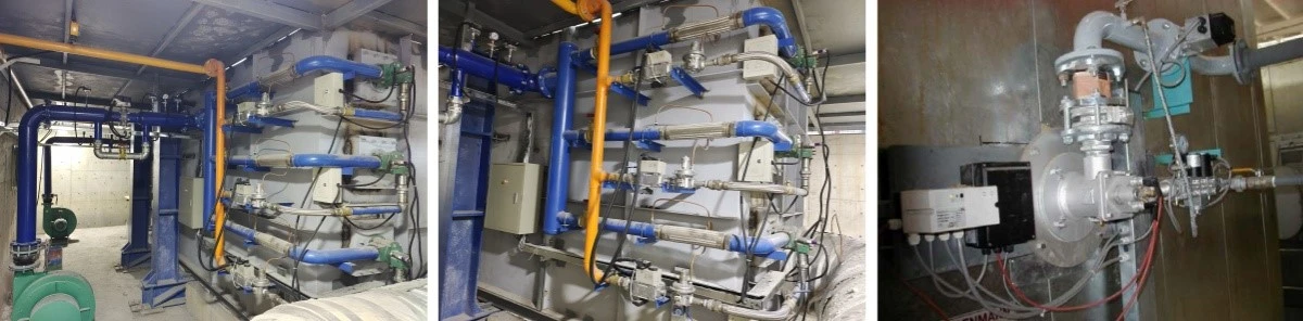
Zinc Pot Burner
Name: Zinc Pot Burner For Structural Components Automatic Hot-dip Galvanizing Production Line
Specification: Customized according to the user's zinc pot specifications.
Overview:
Designed for hot-dip galvanizing of structural components, power fittings, steel pipes, profiles, and other workpieces, this burner is used in conjunction with the XG08 metal zinc pot furnace. Burners are installed diagonally in the combustion chamber, forming a circular flame path.
Each high-speed pulse burner nozzle is equipped with an imported intelligent combustion controller, which enables ignition, power adjustment, and flame-out protection for each nozzle. All nozzles include flame-out alarm devices. The burner operates under automatic control, featuring automatic flame monitoring and safety functions such as power cut-off and valve shutdown in case of anomalies.
Application Parameters
|
Application Position |
Material |
Energy Source |
Application Scope |
|
Zinc Pot Furnace |
Alloy |
Natural Gas + Electricity |
Automatic compression adjustment, high-speed combustion, zinc pot heating |
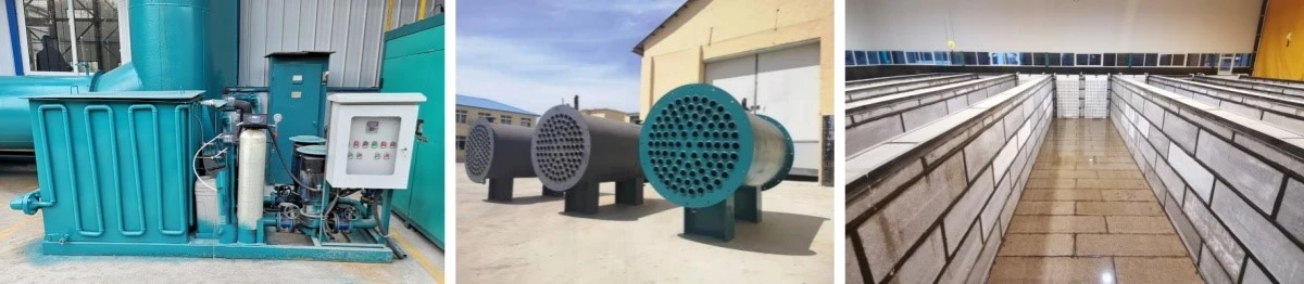
Heat Exchanger
Name: Zinc Pot Furnace Exhaust Gas Heat Recovery System
Specification: The equipment is customized according to the exhaust gas volume of the user's zinc pot furnace.
Overview:
This system recovers waste heat from high-temperature flue gas discharged after heating the zinc pot. Through a two-stage heat exchange process, the residual heat in the flue gas is converted into usable thermal energy to meet process temperature requirements, improve production efficiency, and enhance the working environment, achieving energy saving and low-carbon emission.
A modular high-efficiency tubular heat exchanger is installed in the flue duct to recover waste heat from flue gas at temperatures ranging from 466 to 518°C, heating water to approximately 90°C. Through integration with an insulated heat storage tank, pipelines, a titanium alloy heat exchanger, high-temperature pumps, and an electrical control system, the recovered heat is transferred to the flux tank solution, maintaining it at the optimal process temperature.
Application Parameters
|
Application Position |
Material |
Energy Source |
Application Scope |
|
Furnace Exhaust Gas |
Heat-Resistant Steel |
- |
Recovery of flue gas heat and heating of pre-treatment tank solutions |
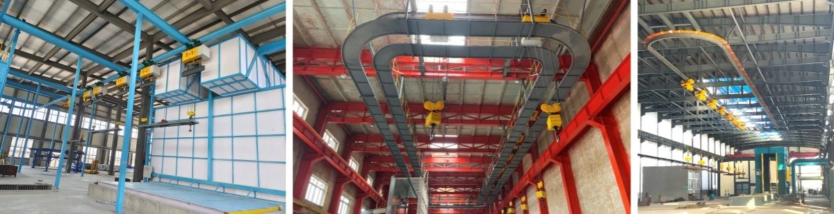
Hot-Dip Galvanizing Circular Rail
Name: Hot-Dip Galvanizing Circular Rail Hoist
Specification: The equipment is customized according to the workpiece specifications and lifting capacity required by the user.
Overview:
This hoist system is designed for hot-dip galvanizing of structural components, power fittings, steel pipes, profiles, and similar workpieces. The galvanizing process adopts a circular rail system, on which 3 to 4 sets of explosion-proof hoists (four-rope, single-line configuration) are installed.
Each hoist has a lifting capacity of 3 to 8 tons. The hoist traveling rail is installed beneath the main workshop beams, with maintenance access space reserved between the rail and the enclosed dust hood.
The system adopts a single-line electric hoist design with a protection rating of IP65. The control mode supports both automatic and manual operation, ensuring safe and efficient material handling throughout the galvanizing process.
Application Parameters
|
Application Position |
Material |
Energy Source |
Application Scope |
|
Hot-Dip Galvanizing Bath |
Steel Structure + Metal |
Electricity |
Orderly transfer of workpieces during galvanizing according to process flow |
Metal Zinc Pot
Name: XG08 Metal Zinc Pot
Specification: The equipment is customized according to the workpiece specifications and production capacity required by the user.
Overview:
This zinc pot is designed for hot-dip galvanizing of structural components, power fittings, steel pipes, profiles, and similar workpieces. It is fabricated from XG08 special steel plates (Ansteel), with a thickness of 60 mm.
The pot features a rounded bottom and corner structure, along with a main rim and secondary rim design. It offers excellent resistance to deformation and a long service life.
On the diagonal sides of the pot (corresponding to the positions of the gas burners), 310S stainless steel plates are installed from top to bottom as fire-resistant linings. These linings prevent localized overheating and damage to the zinc pot near the burners. The 310S stainless steel plates are securely fastened with stainless steel bolts, ensuring strong integrity, resistance to detachment, and extended service life. This design effectively improves the durability of the zinc pot and ensures uniform temperature distribution of the molten zinc.
Application Parameters
|
Application Position |
Material |
Energy Source |
Application Scope |
|
Hot-Dip Galvanizing Bath |
XG08 Metal |
- |
Used for hot-dip galvanizing of workpieces, with molten zinc capacity of 260–1800 tons |

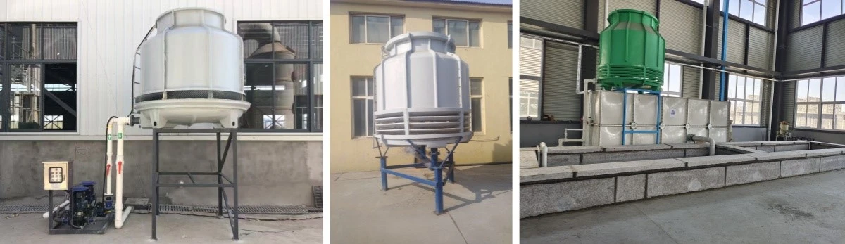
Cooling Tower
Name: Cooling Tower For Structural Components Automatic Hot-dip Galvanizing Production Line
Specification: The equipment is customized according to the specifications of the user's water cooling tank.
Overview:
This system is designed for cooling water temperature reduction after hot-dip galvanizing of structural components, power fittings, steel pipes, profiles, and similar workpieces.
The cooling water treatment system is equipped with a temperature control unit that continuously monitors the water temperature online. When the temperature exceeds 50°C, the system automatically starts the hot water circulation pump.
In winter, the cooling water can be diverted to the pre-treatment tanks for heating purposes, while in summer it is circulated to the cooling tower for forced cooling before returning to the cooling tank.
In addition, the system is equipped with a softened water unit. In case of water-mark quality issues during galvanizing, the system can be manually switched to use softened water.
Application Parameters
|
Application Position |
Material |
Energy Source |
Application Scope |
|
Post-Galvanizing Water Cooling Tank |
FRP (Fiberglass Reinforced Plastic) |
Electricity |
Rapid cooling of water temperature |
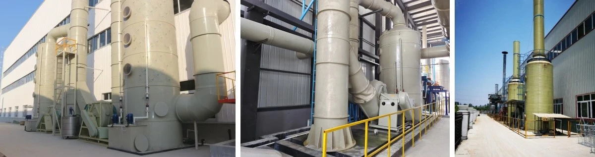
Acid Fume Scrubber Tower
Name: Acid Fume Scrubber Tower For Structural Components Automatic Hot-dip Galvanizing Production Line
Specification: The equipment is customized according to the specifications of the user's enclosed pickling room.
Overview:
This system is designed for treating acid fumes generated during hydrochloric acid pickling in hot-dip galvanizing pre-treatment processes, as well as vapors from rinsing and fluxing operations.
The acid fume exhaust is treated using a water-spray scrubbing method. The system operates by introducing collected acid fumes into a spray chamber, where they come into counter-current contact with the scrubbing solution to achieve effective absorption and purification.
The absorbed solution is periodically replenished into the acid tank for reuse as pickling solution. During normal operation, the system continuously circulates the scrubbing liquid via a water pump to maintain stable absorption efficiency.
Application Parameters
|
Application Position |
Material |
Energy Source |
Application Scope |
|
Pre-treatment Pickling Room |
PP / FRP |
Electricity |
Organized treatment and discharge of exhaust gas from the pickling room |
Dust Removal Equipment
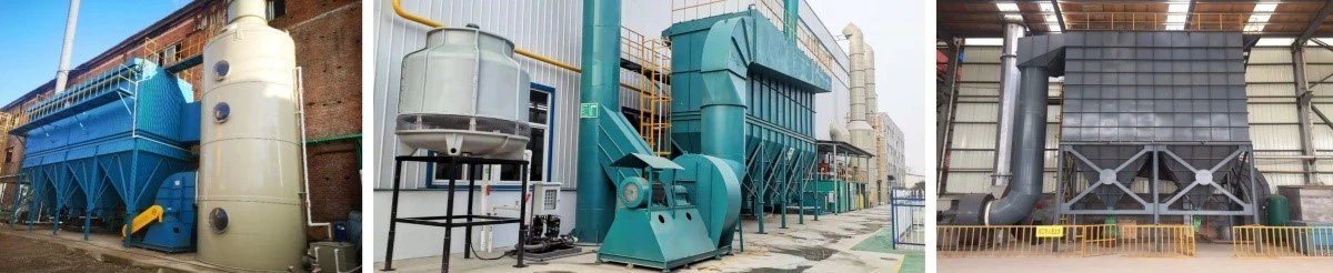
Name: Dust Collector + Ammonia Removal Tower
Specification: The equipment is customized according to the dimensions of the user's zinc pot.
Overview:
This system is designed for the treatment and compliant discharge of dust and fumes generated during the hot-dip galvanizing process.
The bag filter dust collector adopts an optimized pulse-jet cleaning system. Unlike conventional designs that only inject compressed air into the cage frame for a single pulse cleaning, this system enables simultaneous filter bag expansion during pulse injection. When the air is cut off, the filter bags contract and recover, achieving a dual-cleaning effect and significantly improving dust removal efficiency.
The system meets emission requirements with a maximum particulate concentration of 120 mg/m³, and the allowable emission rate for a 15-meter exhaust stack is 3.5 kg/h.
A spray scrubber tower is installed downstream of the dust collector to neutralize ammonia contained in the exhaust gas, ensuring compliant emission.
Application Parameters
|
Application Position |
Material |
Energy Source |
Application Scope |
|
Zinc Pot Dust & Ammonia Treatment |
Carbon Steel + PP |
Electricity |
Organized treatment and discharge of dust and exhaust gas from zinc pot area |

Wastewater Treatment Equipment
Name: Wastewater Treatment System For Structural Components Automatic Hot-dip Galvanizing Production Line
Specification: The equipment is customized according to the wastewater volume generated from the user's pre-treatment tanks.
Overview:
Rinse water from the workshop is pumped into an aerated equalization tank. In this tank, wastewater is treated by blower aeration to regulate flow, homogenize water quality, and achieve pre-oxidation.
The effluent from the equalization tank flows by gravity into a neutralization reaction tank. The wastewater is acidic and contains suspended solids. Under appropriate pH conditions, hydroxide precipitation is formed. When the pH of the wastewater is adjusted above 5.2, the precipitation reaction is largely completed.
However, due to the potential release of soluble iron under acidic conditions, the water after neutralization and coagulation must enter an aeration reaction tank to promote the formation of stable Fe(OH)₃ precipitates.
After sufficient oxidation, stable ferric hydroxide precipitates are formed and transferred to a flocculation tank, where flocculant (PAM) is added. The chemicals and wastewater are fully mixed, and under the adsorption-bridging effect of the polymer flocculant, larger flocs are formed and separated from the water as sediment.
Application Parameters
|
Application Position |
Material |
Energy Source |
Application Scope |
|
Pre-treatment Rinse Tank |
Carbon Steel + PP |
Electricity |
Treatment and purification of pre-treatment rinsing wastewater |

Flux Solution Iron Removal System
Name: Flux Solution Iron Removal System
Specification: The equipment is customized according to the volume of flux solution in the user's pre-treatment flux tank.
Overview:
This system is designed for hot-dip galvanizing of structural components, power fittings, steel pipes, profiles, and similar workpieces. It is used for treating the flux solution in the pre-treatment flux tank based on the required processing capacity.
Practical data shows that when the ferrous ion (Fe²⁺) concentration in the flux solution is too high, it significantly affects zinc consumption and product surface quality. By reducing Fe²⁺ content in the flux solution, this system effectively lowers zinc consumption (total reduction of 5–30%, with an average reduction of 3–10 kg of zinc per ton of workpiece).
In addition, reducing iron ions improves the fluidity of molten zinc, enhances surface quality, and helps prevent defects such as zinc drips and zinc spikes.
Application Parameters
|
Application Position |
Material |
Energy Source |
Application Scope |
|
Pre-treatment Flux Tank |
Carbon Steel + PP |
Electricity |
Iron removal treatment of flux solution |

Automatic Galvanizing Control System
Name: Automatic Galvanizing Control System
Specification: The system is customized according to the user's production line configuration, process requirements, and automation level.
Overview:
This system is designed for centralized control and automation of the hot-dip galvanizing production line, enabling coordinated operation of all process sections including loading, pickling, rinsing, fluxing, drying, galvanizing, cooling, and unloading.
The system integrates PLC control, industrial HMI, and intelligent process management software to achieve real-time monitoring, data acquisition, and automatic adjustment of process parameters such as temperature, lifting speed, dwell time, and line rhythm.
It supports multi-mode operation including automatic, semi-automatic, and manual control, ensuring stable production, improved efficiency, and consistent product quality. Alarm functions, interlocking protection, and fault diagnosis are also included to enhance operational safety and reliability.
Application Parameters
|
Application Position |
Material |
Energy Source |
Application Scope |
|
Entire Galvanizing Line |
Electrical Control System |
Electricity |
Centralized automatic control and process coordination of the galvanizing production line |
Product Advantages
1.Full Process Automation for Unmatched Consistency and Repeatability
The cornerstone of this production line is the integrated Automatic Galvanizing Control System, based on PLC and industrial HMI. This system orchestrates all operations from loading to unloading, automatically managing critical parameters such as hoist lifting/lowering speed, dwell time in the zinc bath, and process temperatures. This eliminates the variability inherent in manual operation, ensuring that every batch of structural components receives identical treatment. The result is a consistently high-quality product with uniform coating thickness and minimal defects, independent of operator skill or fatigue.
2.High-Speed, High-Capacity Production with Circular Rail Design
The system is engineered for maximum throughput. The circular rail design accommodates 3 to 4 sets of explosion-proof galvanizing hoists, allowing for multi-station, parallel processing. While one hoist is in the zinc bath, another can be in the pickling room, and a third can be at the cooling station, all simultaneously. This continuous, coordinated workflow significantly reduces the cycle time per batch, dramatically increasing the overall production capacity of the plant compared to manual or semi-automated lines.
3.Robotic Integration for Complex Processing and High Precision
For specialized galvanizing applications, the production line can be integrated with an advanced robotic hot-dip galvanizing system.These robotic units are programmed to replicate the precise movements and techniques of skilled operators, performing complex operations such as accurate ash removal, controlled immersion at optimized angles, and consistent vibration zinc removal to eliminate excess zinc from critical areas.This robotic automation delivers superior process accuracy, improved production efficiency, and enhanced product consistency. By reducing the need for operators to perform high-risk manual tasks, the system significantly improves workplace safety while ensuring stable and repeatable galvanizing quality.
4.Intelligent Data Acquisition and Real-Time Monitoring for Operational Excellence
The control system provides a comprehensive data acquisition and monitoring interface. Plant managers can view the real-time status of every component and process parameter from a central HMI. The system logs production data, which can be analyzed to identify bottlenecks, optimize processes, and perform predictive maintenance. This data-driven approach provides full traceability and empowers management to make informed decisions that continuously improve plant efficiency and product quality.
5.Superior Zinc Pot Design with 310S Liners for Deformation Resistance
The XG08 metal zinc pot is constructed with a thick 60mm plate and features a round-bottom, rounded-corner design. This geometry is structurally superior, significantly reducing the risk of stress fractures and warpage that can occur in rectangular pots under high heat. The pot also includes 310S stainless steel fire-resistant liners installed on the diagonal walls facing the burners. These liners protect the pot from localized overheating and direct flame impingement, which are primary causes of premature pot failure, ensuring a long service life.
6.Integrated Environmental Control with Automated Systems
This line does not compromise environmental protection for automation. It includes a complete suite of environmental systems: an enclosed pickling room with an acid fume scrubber tower, an enclosed dust hood with a dust collector and ammonia removal tower, and a comprehensive wastewater treatment plant. These systems are integrated with the main control system, allowing for automated monitoring and management of all emissions, ensuring consistent environmental compliance.
7.Scalable and Customizable Modular Architecture
The entire production line is built on a modular principle. This means that the system can be scaled up or reconfigured with relative ease to accommodate changing production demands or future expansion. Whether you need to increase the number of hoists, add a new pre-treatment stage, or integrate a new type of robotic handling, the modular design allows for seamless upgrades without major overhauls of the entire system.
FAQ
Q1: How does the automatic control system ensure consistent product quality when processing different types and sizes of structural components?
The system uses a recipe-based approach. For each product type, an operator can create and store a specific "recipe" in the control system. This recipe contains all the optimal process parameters for that part: the precise lifting speed to minimize splash, the dwell time in the zinc bath to achieve the correct coating weight, and the withdrawal speed for optimum drainage and surface finish. When the operator selects a recipe for a new batch, the PLC automatically implements all these parameters, ensuring each unique product is processed perfectly every time, without any manual adjustment.
Q2: What are the safety features incorporated into the robotic handling system?
Safety is a paramount concern in robotic integration. The robotic system is equipped with multiple safety zones monitored by light curtains and safety scanners. If a person or object enters a designated safety zone, the robot immediately stops its motion. The robot's speed and force are also limited to prevent damage to workpieces or injury to personnel. All robotic operations are interlocked with the main control system, meaning the robot cannot operate if a safety gate is open or if a maintenance lock is engaged.
Q3: What is the purpose of the "vibration zinc removal" function performed by the robotic system?
After a structural component is withdrawn from the zinc bath, it often has excess molten zinc pooling in corners, bolt holes, or other recessed areas. This excess zinc, if left to solidify, can form unsightly and potentially structurally compromising 'zinc drips' or 'spikes'. The robotic system performs a precise 'knock' or vibration sequence. This controlled movement shakes the workpiece, causing the pooled zinc to dislodge and fall back into the zinc pot, resulting in a cleaner, more uniform, and higher-quality coating.
Q4: How does the heat recovery system contribute to the overall efficiency of the line?
The heat recovery system captures waste heat from the furnace's exhaust flue gas (which is typically between 466-518°C) and transfers it via a heat exchanger to heat the flux solution. Without this system, a separate energy source would be required to heat the flux to its optimal temperature (around 60-70°C). By using waste heat, the system drastically reduces the plant's demand for natural gas or electricity for this purpose. This not only lowers energy costs but also reduces the plant's carbon footprint, contributing to a more sustainable and economical operation.
Q5: What is the typical lead time for custom engineering and installation of this automated line?
As this is a highly customized product, the lead time depends on the complexity of the system, its size, and the specific integration requirements. A typical project, from detailed engineering and manufacturing to delivery and full on-site installation, can range from 5 to 12 months. After installation, we provide a comprehensive commissioning and training period to ensure your team is fully proficient in operating and maintaining this advanced system.
Hot Tags: structural components automatic hot-dip galvanizing production line, China structural components automatic hot-dip galvanizing production line manufacturers, suppliers, factory


