


Wire Pay-off
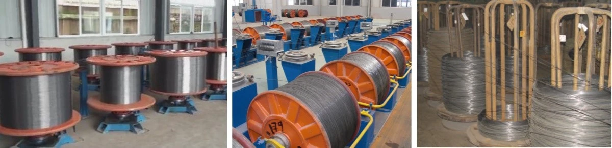
Passive Wire Pay-off
Name: Passive I-beam Wire Pay-off Stand
Overview: Passive I-beam Wire Pay-off Stand is designed for wire spooling in electro-galvanizing and hot-dip coating lines. The equipment consists of a rotating base and a spooling frame. The rotating base is equipped with a tensioning device to control the spooling tension. During production, the spooling frame can be easily replaced.
Active Wire Pay-off
Name: Active I-beam Wire Pay-off Equipment
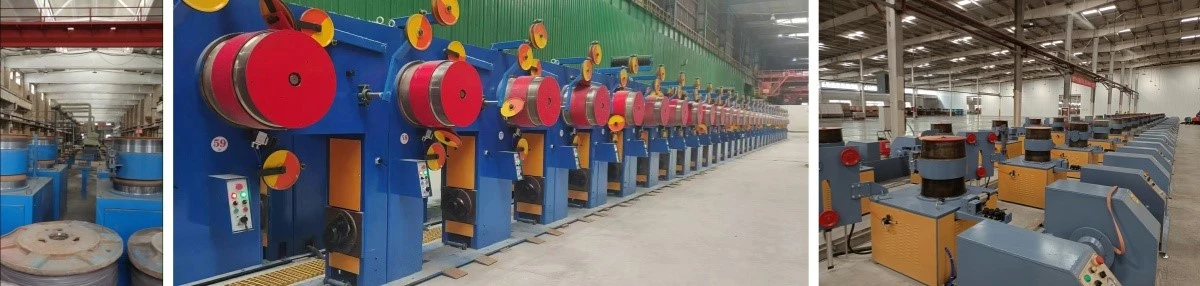
Overview: This system uses a line accumulation type pay-off unit to ensure stable tension without loosening. The wire accumulation time is no less than 3 minutes, and the I-beam can be replaced without stopping the system. The process of replacing the I-beam is simple and easy to operate.
The electrical equipment is housed in an independent control cabinet, along with the winding machine's electrical devices. The pay-off and winding machines are interlocked for coordinated control, with automatic tracking and tension adjustment.
Wire Pay-off Specifications
Customized equipment based on the type of wire products and the user's running speed.
Application Parameters for Wire Pay-off
|
Application Position |
Material |
Applicable Spool Diameter Range |
|
Wire Pay-off |
Metal |
Φ800~Φ1100 (mm) |
Pre-treatment cleaning tank
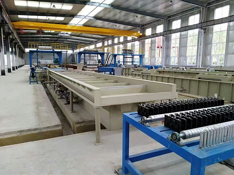
Conventional alkali cleaning tank
Name: Wire Rod Online Conventional Alkali Cleaning Tank
Overview:
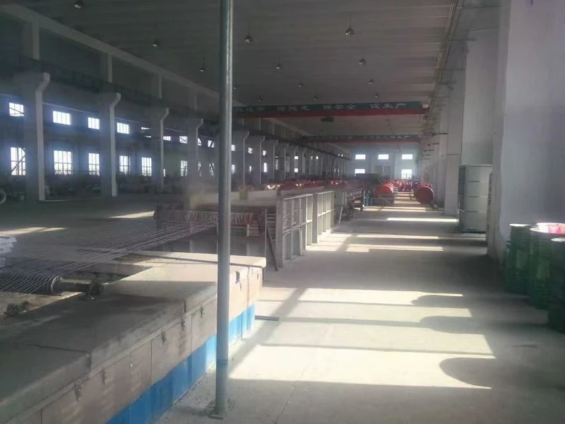
The closed steel wire alkali cleaning process takes place in a completely enclosed space, where the steel wire reaches a clean surface through the scouring of hot alkali solution during production. The closed alkali cleaning tank is made by welding reinforced PP (polypropylene) material plates. A sealing cover is installed on top of the tank, and a ceramic air knife is used at the steel wire outlet to prevent the alkali solution on the wire surface from being carried out, thus avoiding contamination of the subsequent process.
Electrolytic alkali cleaning tank
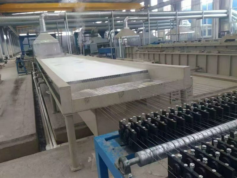
Name: Wire Online Electrolytic Alkaline Cleaning Tank
Overview:
The closed electrolytic alkaline cleaning tank adopts advanced and environmentally friendly electrolytic alkaline cleaning technology. The wire cleaning process takes place in a completely sealed alkaline cleaning space, where the wire is cleaned to a pristine surface under the action of the electrolytic alkaline solution during production. The closed electrolytic alkaline cleaning tank is welded using reinforced PP material panels, and it is equipped with a sealing cover on top. The wire outlet is protected by a ceramic air knife to prevent the alkaline solution from splashing out and contaminating subsequent processes.
The wire electrolytic cleaning tank uses a positive-negative electrode exchange cleaning method and an electrolytic liquid overflow tank for external circulation. The rectifier power supply has a voltage range of 0-12V and an output current of 3000A. Under the electrolytic action and liquid flushing, the wire reaches a clean surface.
Ultrasonic Cleaning Tank
Name: Wire Online Ultrasonic Cleaning Tank
Overview:
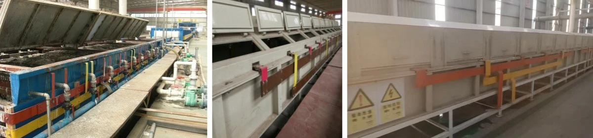
The ultrasonic cleaning tank can replace the functions of both alkaline and acid cleaning tanks, simultaneously removing oil and rust, while shortening the production line length.
The closed overflow-type ultrasonic cleaning technology is used in a fully enclosed cleaning space. It utilizes an environmentally friendly ultrasonic cleaning solution (weak phosphoric acid H₃PO₄ cleaning solution), which is suitable for wire cleaning processes and meets the requirements of hot-dip galvanizing speeds. Ultrasonic cleaning is energy-efficient and environmentally friendly, with no waste acid generated.
The ultrasonic cleaning tank is made from high-strength PP material and equipped with a corrosion-resistant circulating pump. The lower liquid storage tank is divided into two independent parts, A and B. When the liquid in tank A is circulating, the liquid in tank B can be filtered, cleaned, and reused, allowing continuous cleaning of the cleaning solution without halting the production line.
A sealing cover is installed above the cleaning tank to prevent water vapor from escaping. During the cleaning process, the wire is fully immersed in the cleaning solution. The cleaning solution uses two separate liquid storage tanks, each operating independently. The system is equipped with a cleaning solution circulation filtration tank and filtration machine, ensuring the cleaning solution is recycled and reducing material consumption.
Hydrochloric Acid Cleaning Tank
Name: Wire Online Hydrochloric Acid Cleaning Tank
Overview:
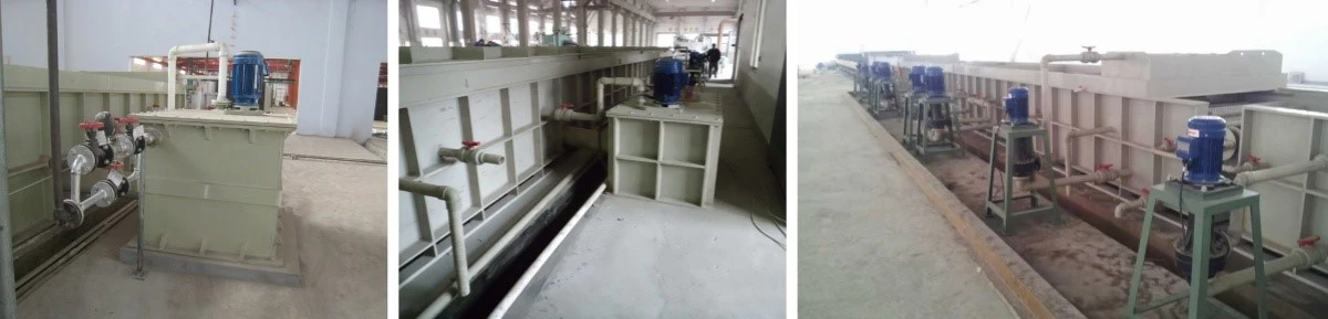
The integrated acid cleaning tank is made of PP (polypropylene) material. During the cleaning process, the wire moves in a straight line. The integrated tank adopts an overflow method, and the tank body is equipped with two corrosion-resistant pumps (4.0 kW power) for water curtain circulation. The acid cleaning tank is equipped with six acid-resistant pumps (0.55 kW power) to provide overflow power for the acid solution. Both the wire inlet and outlet of the tank use dual water curtains for sealing, with a groove sealing method on both sides to prevent acid mist from leaking.
To ensure fast removal of oxide layers from the wire surface and meet the rapid cleaning requirements for galvanizing, the process liquid is cleaned by acid-resistant pumps in a reciprocating motion. This ensures that the wire achieves the required clean surface before galvanizing.
To reduce acid consumption and prevent acid from entering the next process, the acid cleaning tank's outlet is equipped with a flow-blocking stone and a blowback system to remove any residual acid from the surface of the wire.
Water Cleaning Tank
Name: Wire Online Water Cleaning Tank
Overview:
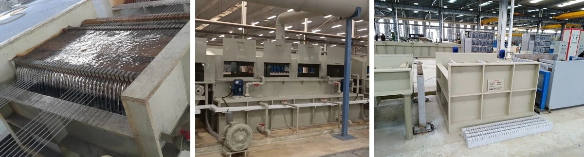
The tank body is welded using acid-resistant materials. To quickly and efficiently remove residual impurities from the wire surface, the tank adopts a two-stage overflow cleaning system with separate circulation and reverse water inlet and outlet methods. Each tray is equipped with a corrosion-resistant vertical pump (motor power 0.55 kW) to provide overflow power. During the overflow cleaning process, the water enters the cleaning tray in a spray form, and the cleaning water can be recycled, saving water consumption and reducing wastewater discharge.
To prevent cleaning water from contaminating the next process, the outlet of the cleaning tank is equipped with a flow-blocking stone and a blowback air knife (with a 5.5 kW fan) to remove any residual cleaning water from the wire surface. The design is fully enclosed, with an accessible wire insertion cover and a reserved air intake for the purification tower.
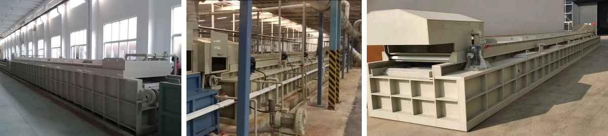
Galvanizing Aid Solvent Cleaning Tank
Name: Wire Online Galvanizing Aid Solvent Cleaning Tank
Overview:
The closed galvanizing aid solvent cleaning tank is welded using reinforced PP (polypropylene) material panels. A layer of ammonium chloride aqueous solution is applied to the surface of the wire to prevent secondary oxidation and to enhance the adhesion between the wire and the zinc solution during galvanizing. The solvent cleaning tank adopts an overflow circulation method.
A sealing cover is placed above the closed electrolytic alkaline cleaning tank, and the wire outlet is equipped with a ceramic air knife to prevent the alkaline solution from being carried out with the wire, thus avoiding contamination of subsequent processes.
Pre-treatment Cleaning Tank Specifications
Customizing appropriate equipment based on the user's wire product type and line speed.
Pre-treatment Cleaning Tank Application Parameters
|
Application Position |
Material |
Energy Source |
DV Value |
Applicable Wire Diameter Range |
|
Wire Pre-treatment Cleaning |
PP panels, Stainless Steel |
Electric Energy |
40~200 mm·m/min |
Φ0.8–Φ8.0 (mm) |
Drying Furnace
Name: Wire Online Drying Equipment For Hot Dip Galvanized High Carbon Steel Wire Equipment
Overview:
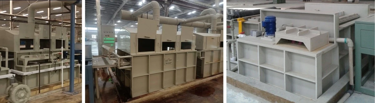
The drying furnace can be powered by electric energy, natural gas, or furnace gas for heating. The furnace body is constructed with 304 material and a Q235 steel structure welded together. The internal insulation of the furnace is made from high-temperature silica-alumina fiber materials.
The heating of the furnace chamber is achieved through hot air circulation ducts. A ventilation fan is arranged at the rear of the furnace. After passing through the galvanizing aid tank, the wire surface still retains residual water. To prevent the wire from causing zinc splashing when immersed in the zinc bath and to avoid uneven zinc coating, the wire must undergo a drying process after the galvanizing aid treatment.
Drying Furnace Specifications: The specifications of the drying furnace are customized based on the user's wire product type and line speed.
Drying Furnace Application Parameters
|
Application Position |
Material |
Energy Source |
DV Value |
Applicable Wire Diameter Range |
|
Wire Pre-galvanizing Drying |
Metal materials + Insulation |
Electric energy, Natural gas |
40~180 mm·m/min |
Φ0.8~Φ8.0 (mm) |
Zinc Bath
Metal Zinc Bath
Name: Metal Hot-Dip Galvanizing Bath
Specification: Customized based on the user's energy requirements and line speed.
Overview:
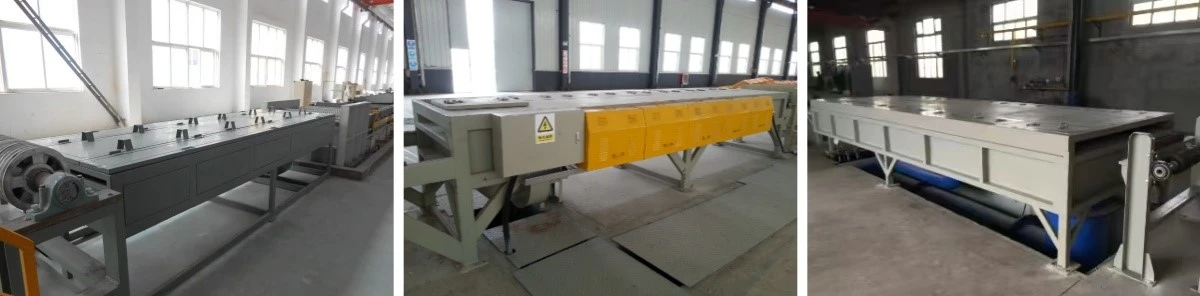
Customized to meet the user's energy needs, wire diameter, DV value, and wire production volume, with a zinc capacity ranging from 35 to 180 tons. The metal Zinc Bath is made from XG08 metal material or stainless steel, used in conjunction with a furnace. The heating method is external heating, and the energy source can be either electric energy or natural gas.
The temperature control system uses corrosion-resistant thermocouples to ensure accurate and stable zinc temperature by allowing direct contact with the molten zinc. The Zinc Bath has a service life of 5 to 8 years.
Application Parameters
|
Application Position |
Material |
Energy Source |
DV Value |
Applicable Wire Diameter Range |
|
Hot-Dip Galvanizing Pot |
XG08 metal material + stainless steel |
Electric energy, Natural gas |
40~200 mm·m/min |
Φ0.8~Φ8.0 (mm) |
Ceramic Zinc Bath
Name: Internal Heating Ceramic Zinc Bath
Specification: Customized based on the user's wire product type and line speed.
Overview:
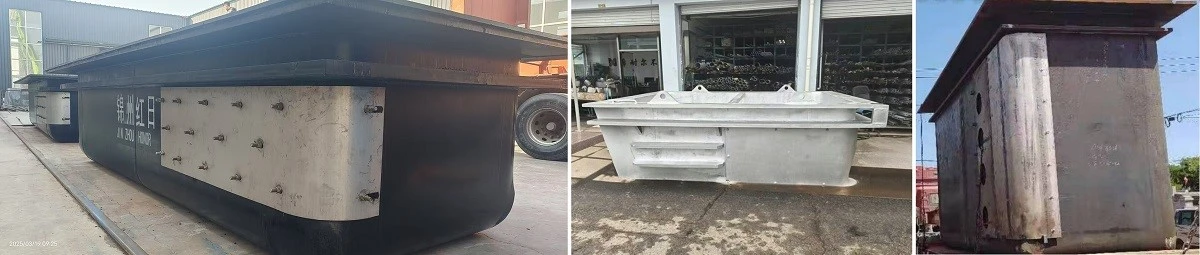
The equipment is customized according to the user's wire diameter, DV value, and wire production volume, with a molten zinc capacity of 35 to 180 tons. It features a steel shell with a ceramic inner lining and an internal heating structure. The heating system is installed on the inner wall of the Zinc Bath to ensure the temperature of the molten zinc is uniform across the working area. Corrosion-resistant thermocouples are used to monitor the temperature, and these thermocouples come into direct contact with the molten zinc, ensuring stable and accurate temperature control. The service life of the Zinc Bath is over 10 years.
Application Parameters
|
Application Position |
Material |
Energy Source |
DV Value |
Applicable Wire Diameter Range |
|
Hot-Dip Galvanizing Pot |
Steel structure + ceramic |
Electric energy, Natural gas |
40~200 mm·m/min |
Φ0.8~Φ8.0 (mm) |
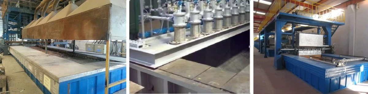
Gantry Frame
Name: Zinc Bath Gantry Frame (Vertical Steel Frame) For Hot Dip Galvanized High Carbon Steel Wire Equipment
Specification: Customized based on the user's wire product type and line speed.
Overview:
Customized to meet the user's wire diameter, DV value, and wire production volume. The Zinc Bath is installed with a set of vertical steel frames to ensure that the equipment operates smoothly without shaking, allowing for stable hot-dip galvanizing of the wire. The vertical steel frame is constructed using profile steel structures. Additional auxiliary equipment, such as wire support shafts, cooling systems (air and water), wire guide shafts, steel wire guiding shafts, and wiping frames, are mounted on the steel frame to aid in the galvanizing process.
Application Parameters
|
Application Position |
Material |
Energy Source |
DV Value |
Applicable Wire Diameter Range |
|
Hot-Dip Galvanizing Zinc Bath |
Steel structure |
- |
40~200 mm·m/min |
Φ0.8~Φ8.0 (mm) |
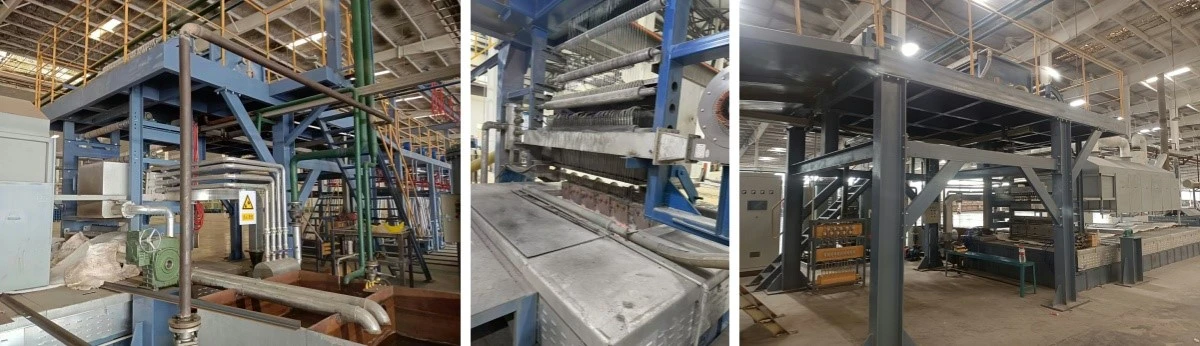
Ceramic Pressing Shaft
Name: Synthetic Nitride Ceramic Pressing Shaft For Hot Dip Galvanized High Carbon Steel Wire Equipment
Specifications: Customized according to the type of wire products and drawing speed.
Overview:
The wire pressing rollers are made from synthetic nitride ceramic sintering. The ceramic wire pressing rollers come in two independent structural forms: high zinc and regular zinc, with the same installation position, ensuring the required zinc layer weight and reducing production costs. The nitride ceramic wire pressing rollers offer high strength, excellent wear resistance, and good corrosion resistance to molten zinc. The wire pressing roller assembly adopts a two-stage gearbox reversing structure, allowing for adjustable wire exit angles. The service life is greater than or equal to 5 years.
Application Parameters
|
Application Position |
Material |
Energy Source |
DV Value |
Applicable Wire Diameter Range |
|
Hot-Dip Galvanizing Zinc Bath |
Silicon Nitride |
- |
8 to 60 wires |
Φ0.8~Φ8.0 (mm) |
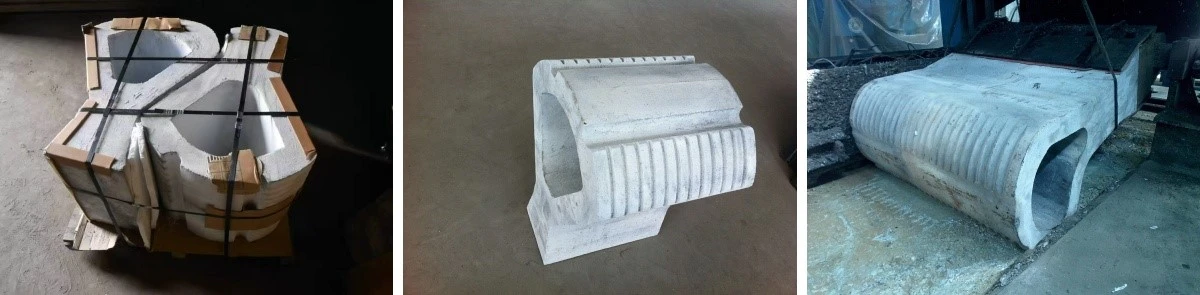
Wiping System
Name: Wire Hot-Dip Galvanizing Wiping System
Specifications: Customized according to the wire diameter, DV value, and wire output requirements.
Overview:
The wire wiping method is selected based on the product's zinc layer thickness, DV value, and wire output requirements. The available wiping methods include fiber pressure block wiping, nitrogen air knife wiping, electromagnetic wiping, and traditional charcoal wiping techniques. These methods are used to control the zinc layer thickness on the wire surface. The zinc layer thickness can be controlled within a range of 50 to 460 g/m².
Application Parameters
|
Wiping Method |
Number of Steel Wires |
DV Value |
Applicable Wire Diameter Range |
|
Fiber Pressure Block Wiping |
36-42 wires |
60-90 mm·m/min |
Φ0.8-Φ8.0 mm |
|
Nitrogen Protection Wiping |
32-42 wires |
60-120 mm·m/min |
Φ0.8-Φ8.0 mm |
|
Nitrogen Air Knife Wiping |
12-22 wires |
80-200 mm·m/min |
Φ0.8-Φ8.0 mm |
|
Electromagnetic + Nitrogen Wiping |
12-22 wires |
80-200 mm·m/min |
Φ0.8-Φ8.0 mm |
|
Charcoal Wiping |
22-60 wires |
40-50 mm·m/min |
Φ0.8-Φ8.0 mm |
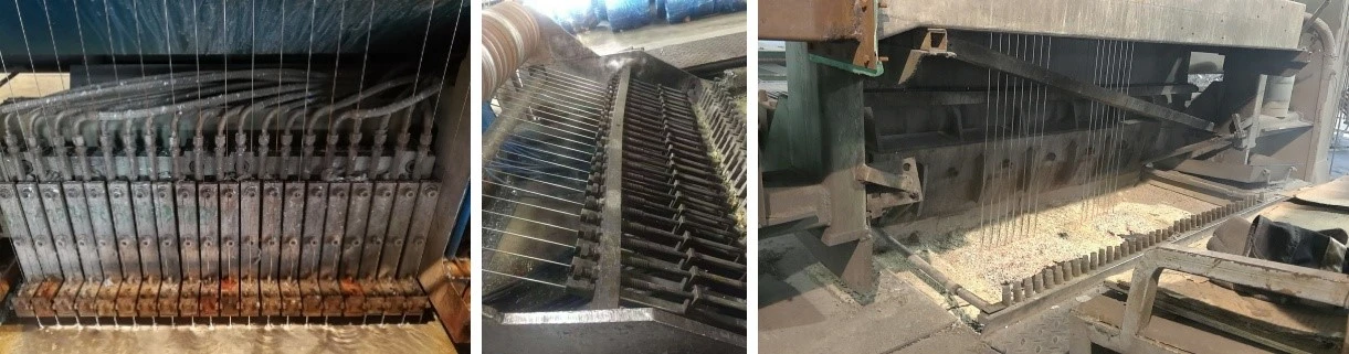
Zinc Coating Control System
Name: Wire Hot-Dip Galvanizing Online Zinc Coating Detection System
Specifications: Customized according to the type of wire products and drawing speed.
Overview:
This system is suitable for wire hot-dip galvanizing lines equipped with nitrogen wiping systems and electromagnetic wiping systems. The online zinc coating detection uses a comparison-based detection and control method. During production, the required zinc layer thickness is set on the HMI, with a typical zinc layer deviation value (usually within ±20g). The detection instrument transmits real-time data to the PLC, which adjusts the electromagnetic valve of the nitrogen pipeline based on the detection data. This adjustment controls the flow and pressure of the nitrogen air knife, which in turn controls the zinc coating thickness. The system is easy to operate and adjust, making it more convenient for users.
Application Parameters
|
Application Position |
Material |
Energy Source |
DV Value |
Applicable Wire Diameter Range |
|
After Wire Galvanizing |
Metal |
Electric Power |
100-200 mm·m/min |
Φ1.2-Φ8.0 mm |
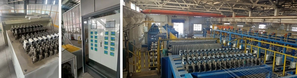
Wire Take-Up Unit
Name: Wire Take-Up Unit for Hot Dip Galvanized High Carbon Steel Wire Equipment
Specifications: Customized according to the type of wire products and drawing speed.
Overview:
The equipment is customized based on the wire diameter, DV value, and wire output requirements. It is suitable for use after hot-dip galvanizing or electro-galvanizing of steel wire. The appropriate winding machine is selected based on the post-galvanized wire diameter, material, and intended use. The winding weight range is from 35 to 2000 kg.
Application Parameters
|
Winding Machine Type |
Material |
Energy Source |
Applicable Wire Diameter Range |
Reel Weight |
|
Horizontal Winding Machine |
Metal |
Electric Power |
Φ1.0–Φ6.0 mm |
0.2–0.8t |
|
Star Inverted Winding Machine |
Metal |
Electric Power |
Φ1.2–Φ8.0 mm |
0.8–2.0t |
|
Spool Winding Machine |
Metal |
Electric Power |
Φ0.6–Φ8.0 mm |
0.5–0.8t |
|
Elephant Nose Winding Machine |
Metal |
Electric Power |
Φ0.6–Φ1.6 mm |
20–50 kg |

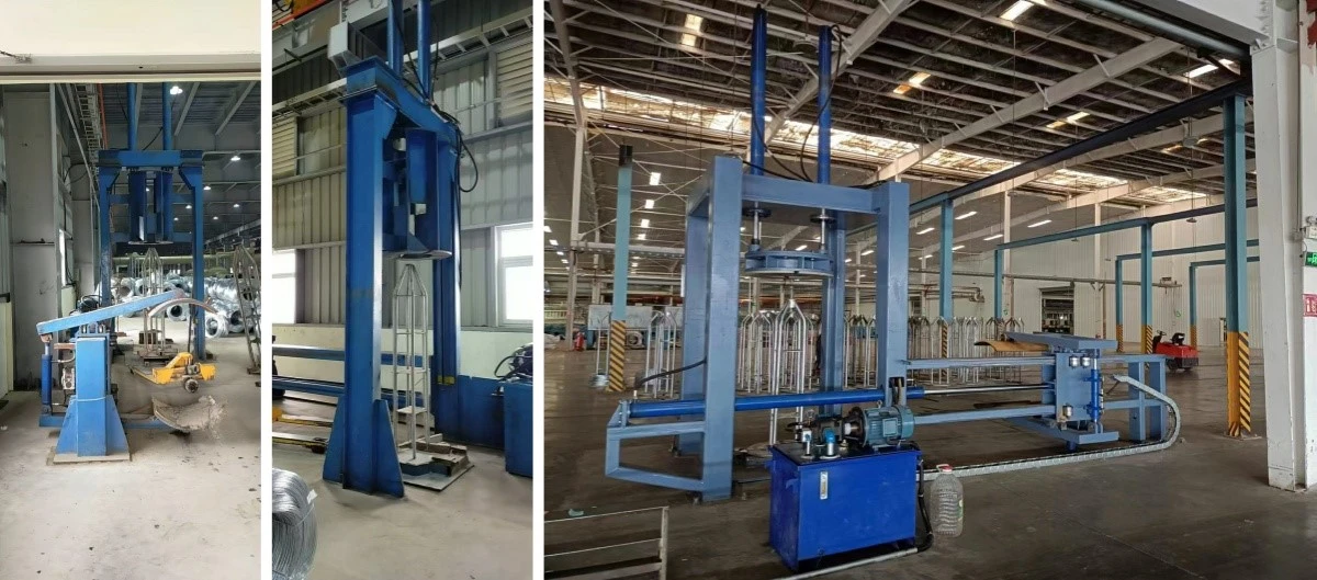
Bundling Machine
Name: Wire Bundling Machine For Hot Dip Galvanized High Carbon Steel Wire Equipment
Specifications: Customized according to the wire product's intended use.
Overview:
This machine is suitable for use after winding large steel wire that has undergone hot-dip galvanizing or electro-galvanizing. The hydraulic Bundling Machine's main frame is welded from section steel, making it a full-metal structure. The top is designed with a dual hydraulic cylinder structure, and the hydraulic cylinders are attached to the lower pressure basket with screws for easy transportation. The machine adopts a long-arm extension structure to accommodate coil weights ranging from 800 to 2000 kg.
Application Parameters
|
Application Position |
Material |
Energy Source |
Applicable Wire Diameter Range |
Coil Weight |
|
After Wire Winding and Strapping |
Metal |
Electric Power, Hydraulic |
Φ1.6–Φ8.0 mm |
0.8–2.0t |
Product Advantages
1.Advanced Multi-Stage Pre-Treatment System for High Carbon Steel Wire
High carbon steel wire requires a more aggressive and precise surface preparation process due to the presence of stubborn drawing lubricants, oil residues, and surface oxides generated during wire processing.
This system incorporates a comprehensive multi-stage pre-treatment solution, combining conventional alkaline cleaning, high-performance electrolytic alkaline cleaning with a 3000A high-power rectifier, and an optional ultrasonic cleaning module to achieve superior surface activation.
The electrolytic cleaning process, featuring polarity reversal between positive and negative electrodes, delivers powerful deep-cleaning performance beyond conventional chemical treatment methods. This advanced cleaning technology ensures complete removal of contaminants and creates an exceptionally clean wire surface, providing the ideal foundation for strong metallurgical bonding between the steel substrate and zinc coating.
A contaminant-free surface is critical for achieving reliable coating adhesion and preventing premature coating failure in demanding applications, including power transmission, telecommunications, and cable industries.
2.Superior Wear Resistance with Silicon Nitride Ceramic Wire Guide Components
The application of advanced silicon nitride ceramic components provides a significant technological advantage in continuous hot-dip galvanizing of steel wire.
Silicon nitride ceramic rolls offer outstanding hardness, excellent wear resistance against high-speed moving wire, and exceptional corrosion resistance in molten zinc environments.
Unlike traditional metal guide rolls, which gradually deform and wear during long-term operation-causing instability in wire positioning and inconsistent coating thickness-ceramic rolls maintain their original dimensions and surface performance for extended service periods.
This ensures highly consistent zinc coating weight across the entire wire length, reduces material waste, improves product quality, and helps high-strength steel wire meet stringent requirements for safety-critical applications.
3.Flexible Wiping Technology for Precise Coating Weight Control
The system is equipped with multiple wiping solutions to meet different coating requirements, including fiber pad wiping, nitrogen gas wiping (air knife technology), electromagnetic wiping, and conventional charcoal wiping.
This flexible configuration allows manufacturers to accurately control galvanized coating weight according to specific application requirements. The system supports a wide coating range from 50 to 460 g/m², providing optimized solutions for various wire products and end-use industries.
4.Closed-Loop Coating Control for Real-Time Quality Assurance
The integrated online zinc coating measurement system represents a significant advancement in galvanizing process automation.
Operators only need to set the target coating weight and allowable deviation range through the user-friendly HMI interface, and the system automatically manages the coating control process.
The online measuring device continuously monitors the actual zinc coating weight and transmits real-time data to the PLC control system. Based on the feedback data, the PLC automatically adjusts nitrogen air knife pressure and flow rate through precision control valves, forming a fully automated closed-loop feedback control system.
This ensures that coating weight remains consistently within the specified range, significantly reducing operator intervention, minimizing zinc consumption caused by over-coating, and guaranteeing stable, uniform, and high-quality galvanized wire production.
5.Durable PP Construction for Superior Chemical Resistance and Extended Service Life
All pre-treatment tanks are manufactured from high-strength reinforced polypropylene (PP), a material specifically selected for its outstanding resistance to aggressive acids, alkaline solutions, and chemical cleaning agents used throughout the pre-treatment process.
This robust construction minimizes maintenance requirements and extends equipment service life, even under the continuous and demanding operating conditions typical of high carbon steel wire galvanizing production.
The modular design also simplifies maintenance operations and enables future system upgrades, ensuring long-term reliability and sustained production value.
6.Seamless Integration of Active Pay-Off and Wire Accumulator Technology
The active pay-off system is equipped with an integrated wire accumulator capable of storing at least three minutes of continuous wire supply.
This essential buffer function allows operators to replace empty wire coils without stopping the production line, ensuring uninterrupted operation.
The pay-off and take-up units are intelligently interconnected for synchronized control, featuring automatic wire tension monitoring and adjustment.
This seamless integration eliminates costly production downtime, maintains smooth and continuous wire processing, and maximizes overall production efficiency-particularly critical for high-speed, high-volume high carbon steel wire galvanizing operations.
FAQ
Q1: What specific measures are taken to prevent hydrogen embrittlement during hot-dip galvanizing of high carbon steel wire?
Hydrogen embrittlement is a critical concern when processing high carbon steel because hydrogen can be absorbed during the pickling process. Our galvanizing process is specifically designed to minimize this risk through optimized pre-treatment technology.
The pre-treatment cleaning system utilizes carefully controlled pickling conditions, including reduced acid concentration and the application of corrosion inhibitors, to minimize hydrogen generation and absorption during surface preparation.
In addition, the optional ultrasonic cleaning module can significantly reduce, or in some cases eliminate, the need for aggressive acid pickling. Since strong acid pickling is one of the primary sources of hydrogen introduction, this advanced cleaning approach further reduces the risk of hydrogen embrittlement while maintaining excellent surface cleanliness and coating adhesion.
Q2: What is the expected service life of the ceramic guide roll? What signs indicate that replacement is required?
The silicon nitride ceramic guide roll is designed to provide a service life of 5 years or more under normal operating conditions. However, the actual service life may vary depending on factors such as wire speed, tension, operating conditions, and the specific characteristics of the high carbon steel wire being processed.
Key indicators that replacement may be required include visible wear, such as grooves, surface damage, or chipping on the ceramic roll. Excessive wear can negatively affect wire stability, resulting in reduced coating uniformity and increased standard deviation in coating weight measurements recorded by the online control system.
Regular visual inspections and periodic wear measurements are recommended to proactively monitor roll condition. By identifying wear in advance, replacement can be scheduled during planned maintenance periods, helping to avoid unexpected production downtime and maintain stable galvanizing quality.
Q3: Can the electromagnetic wiping system be retrofitted to an existing production line currently using fiber pad wiping?
Yes. The electromagnetic wiping system is designed with a modular structure and can be integrated into most existing galvanizing lines.
Although fiber pad wiping systems offer simpler mechanical operation and lower initial investment costs, the electromagnetic wiping system can be added as an advanced upgrade solution.
The retrofit process typically involves installing electromagnetic wiping heads on a support frame above the zinc bath, connecting dedicated power supply and control systems, and configuring the PLC software to integrate the new wiping technology into the existing production line.
Our engineering team can provide a customized retrofit plan based on site conditions, ensuring minimal downtime and a smooth transition. This upgrade delivers significant advantages for high-speed galvanizing lines requiring ultra-smooth surfaces, precise coating control, and consistent thin coating performance.
Q4: How does the active pay-off system with wire accumulator technology operate during wire coil replacement?
The active pay-off system is designed to maintain continuous production during wire coil replacement.
When the current wire spool is approaching the end of its wire supply, the system automatically alerts the operator. The production line then seamlessly switches to drawing wire from the wire accumulator, which stores at least three minutes of continuous wire supply.
This provides a safe operating window for the operator to stop the empty spool, install a new full spool, and complete the wire joining process without interrupting production.
By eliminating costly production downtime, the system ensures smooth and uninterrupted operation, maximizing overall plant efficiency and productivity.
Q5: What is the function of the ceramic air knife in the pre-treatment section?
The ceramic air knives are strategically installed at the outlet of each pre-treatment tank. Their primary function is to prevent process solutions from being carried over from one treatment stage to the next.
As the steel wire exits each tank, the air knife directs a precisely controlled high-pressure airflow onto the wire surface, effectively removing residual liquid before entering the following process stage.
This is essential for maintaining the chemical balance and concentration of each treatment bath, reducing chemical consumption, and preventing cross-contamination that could negatively affect final coating quality and adhesion.
Q6: What are the differences between a metal zinc pot and a ceramic zinc pot for high carbon steel wire galvanizing?
The main differences lie in the heating method, temperature uniformity, and service life.
A traditional metal zinc pot, typically manufactured from XG08 steel, uses an external heating system and generally provides a service life of approximately 5–8 years under normal operating conditions.
In comparison, the ceramic zinc pot adopts an internal heating system combined with a ceramic lining structure. This design provides superior thermal efficiency, more uniform temperature distribution throughout the molten zinc bath, and a significantly extended service life of more than 10 years.
For high carbon steel wire galvanizing applications, ceramic zinc pots are often preferred due to their excellent thermal stability and precise temperature control. These advantages help maintain consistent coating quality, reduce zinc dross formation, and improve overall production efficiency when processing high-strength steel wire.
Hot Tags: hot dip galvanized high carbon steel wire equipment, China hot dip galvanized high carbon steel wire equipment manufacturers, suppliers, factory


